
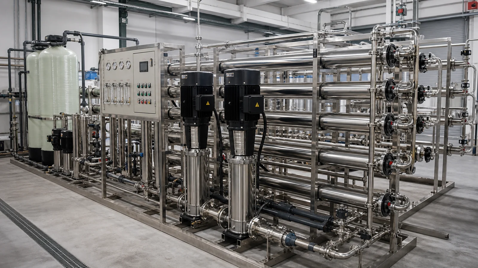
Industrial Process Water RO System
Plan an industrial process water RO system from feed analysis, production demand and target conductivity, with single-pass or double-pass equipment routes.
When this solution is appropriate.
This route suits manufacturing rinse water, ingredient or process preparation, cooling-system makeup and general low-salinity process water. Final selection starts with the feed-water report and use-point requirement, not a nominal flow label alone.
- Use single-pass RO when one membrane pass can meet the required conductivity and recovery target.
- Use double-pass RO when lower conductivity or a more stable second desalination step is required.
- Review UF or additional pretreatment first when turbidity, colloids or seasonal source-water variation are significant.
Data that controls the final configuration.
These inputs determine pretreatment, process stages, equipment size, storage and control scope before a technical quotation is confirmed.
- Source water
- Confirm municipal, well, surface or recycled feed and provide a recent laboratory analysis.
- Demand profile
- State hourly flow, daily volume, operating shifts, peak demand and planned expansion.
- Feed chemistry
- Include TDS, hardness, alkalinity, silica, iron, manganese, turbidity and residual chlorine.
- Product target
- Define conductivity, TDS, recovery and the process or equipment served by the water.
- Utilities
- Confirm voltage, frequency, feed pressure, drain availability and instrument-air needs.
- Site limits
- Provide room dimensions, access, tank positions, connection sizes and ambient temperature.
Recommended treatment sequence.
Optional stages are included only when the feed analysis, operating profile or final water requirement supports them.
- Source tank and feed pumpStabilize feed flow and provide the pressure required by pretreatment.
- Selected pretreatmentUse media filtration, iron removal or UF according to suspended solids and source variation.
- DechlorinationProtect polyamide RO membranes with activated carbon or controlled chemical reduction.
- Scale controlUse softening, antiscalant or pH adjustment according to saturation calculations.
- Cartridge filtrationProvide the final particulate barrier immediately before the high-pressure pump.
- Single-pass or double-pass ROSelect the membrane route from feed conditions, recovery and final conductivity.
- Product tank and deliveryBuffer production and match downstream peak demand.
- UV or ozoneAdd downstream disinfection only when storage time and application controls require it.
Engineering values to confirm during selection.
These are design references, not unconditional guarantees. Final values depend on the supplied water analysis, equipment selection and operating conditions.
| Parameter | Reference | Design note |
|---|---|---|
| Feed TDS | Laboratory result required | Controls membrane type, pressure, array and expected permeate quality. |
| RO feed SDI | Below 5 | Pretreatment must be reviewed when the target cannot be maintained. |
| RO feed turbidity | Below 1 NTU | Reference limit before the membrane train. |
| Residual chlorine | Below 0.1 mg/L | Confirm at the RO inlet to protect polyamide membranes. |
| Single-pass recovery | 50-75% reference | Final value depends on feed chemistry, temperature and array design. |
| Product conductivity | Set by project | Validate against feed water, membrane selection and number of passes. |
| Operating schedule | Project-specific | Continuous and intermittent plants require different tank and flushing logic. |
Core equipment and controls.
- Feed and pretreatment pumps selected for the confirmed hydraulic duty
- Pretreatment vessels or membrane modules required by the feed analysis
- Cartridge filter, high-pressure pump and RO pressure vessels
- Online pressure, flow and conductivity instruments
- PLC control with low-pressure protection and automatic flushing
- Skid piping, valves and electrical cabinet for the agreed battery limits
Items selected from project data.
- Double-pass RO for lower final conductivity
- UF pretreatment for variable or high-colloid feed water
- CIP cleaning skid and membrane-preservation connections
- Product tank, delivery pump, UV, ozone or remote monitoring
Commissioning and maintenance priorities.
- Record feed pressure, differential pressure, permeate flow, recovery and conductivity at commissioning.
- Trend normalized permeate flow and salt passage so fouling is identified before output collapses.
- Replace cartridge filters from pressure drop and inspect pretreatment performance before RO cleaning.
- Confirm chemical dosing, reject-water routing and automatic flushing during operator training.
Questions before equipment selection.
What data is needed before selecting an industrial RO system?
Provide a recent feed-water analysis, hourly and daily demand, operating schedule, target conductivity, voltage and site constraints.
Can a standard RO skid guarantee the same conductivity for every source water?
No. Product quality changes with feed composition, temperature, recovery, membrane selection and the number of RO passes.
What should be recorded during commissioning?
Record feed and stage pressures, flows, recovery, conductivity, temperature and chemical settings as the baseline for future maintenance.
Compare the product routes for this solution.
Turn the application data into a quotation.
Send the water analysis, required hourly and daily output, operating hours, target conductivity, voltage, destination and site layout.